With AIP H2 test benches, tests and characterizations are carried out on Fuel Cell Membrane Electrode Assemblys (H2 FC-MEA), Fuel Cell Stacks (H2 FC-STACK) or on Electrolyser Cells / Stacks (H2 EC Electrolyser) under defined and reproducible operating conditions.
- The AIP H2 test benches are based on a modular system and are designed to be self-sufficient and flexible
- In-House developed test bench automation system for all hydrogen test benches (AIP-MCS)
- Production and software from one source
H2 EC-Electrolyseur
Features
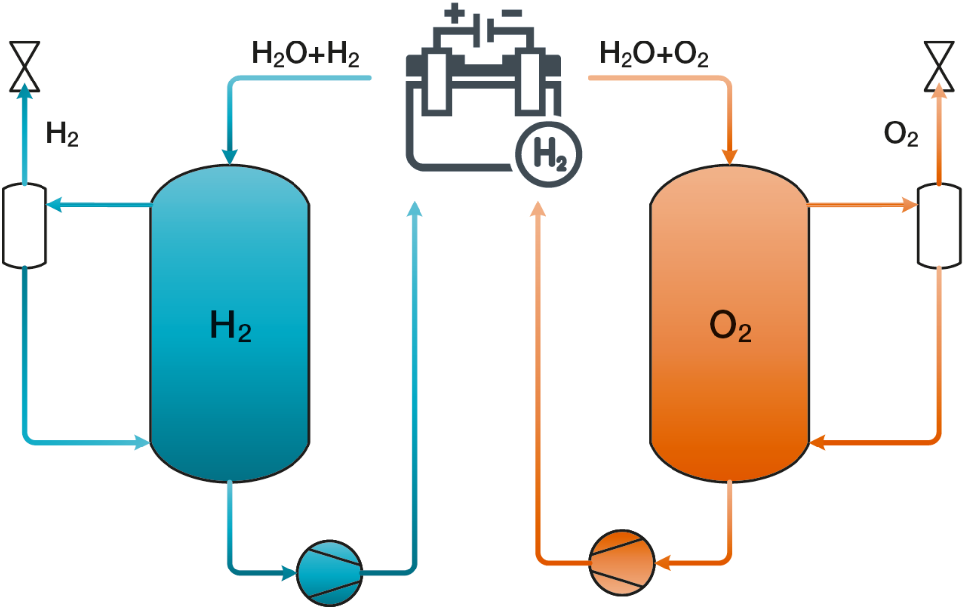
- Dynamic pressure control at cathode and anode
- Gas volume flow measurement at anode and cathode (H2 and O2)
- Measurement of dewpoint, pressure, and temperature after the cell
- Drying of the product gases H2 and O2 by tube bundle heat exchangers
- Pressurized DI water supply with integrated ion exchanger
- Electronic power supply (optional)
- Automatic condensate separation with sampling option
- Inerting in the event of a fault with nitrogen at cathode and anode
- Plausibility and monitoring functions (H2 warning unit, flow monitoring exhaust air system, leak test, monitoring of customer media, ...)
- Automated, unmanned operation
- Modular DAQ system for data acquisition and data visualization
- Possibility of connection to the customer’s ATEX exhaust air system
- Cooling circuit for tempering the DUT (optional)
- Impedance spectroscopy (EIS) to characterize the cells, including Cyclovoltammetry and linear sweep voltammetry (optional)
- Cell voltage monitoring up to 800 channels (optional)
Application
- Separation of water (H2O) into hydrogen H2 and oxygen O2
Technical Specifications
|
Product gas treatment
|
| Gas cooler |
Tube bundle heat exchanger |
|
| Gas cooling capacity |
up to 4 |
°C |
| Mass Flow Sensors accuracy |
± 0.1 |
% FS |
| ± 0.5 |
% RD |
| Pressure control range |
1.1 – 50 |
bar |
| Pressure control accuracy |
< 25 |
mbar |
| Pressure sensor accuracy |
± 0,25 |
% FS |
| Temperature sensors |
PT100 |
|
|
Power supply (depends e.g. on customers specific supplication)
|
| Voltage |
0 – 60 |
V |
| Current max. |
1,014 |
A |
| Power max. |
27 |
kW |
| Functions |
U / I / P autoranging |
|
|
Tempering unit (example)
|
| Temperature stability |
± 0.02 |
K |
| Regulation modes |
T |
|
| Pressure control range |
pressureless (pressurized on request) |
|
| Temperature control range |
-30 ... 200 |
°C |
| Cooling media |
DI - water or DI water glycole mixture |
|