
Batterie
Sichern Sie die Entwicklung belastbarer und zertifizierbarer Batteriesysteme – vom Prototyp bis zur Serie. Batterien sind das Herz moderner Antriebssysteme. Ihre Leistungsfähigkeit und Sicherheit bestimmen die Effizienz Ihres neuen Meisterwerks. Testen Sie Batterien und komplette Energy-Packs unter realitätsnahen Bedingungen. Erfassen Sie Lade- und Entladezyklen, Temperaturverhalten und Alterung präzise und reproduzierbar.
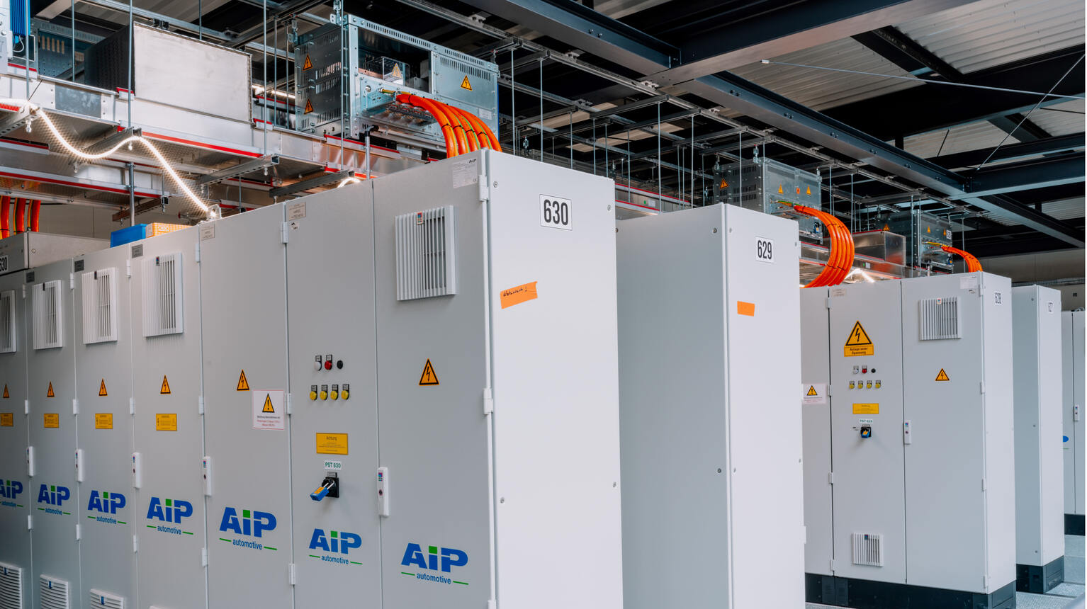
Intelligente Prüfstände für Batterien


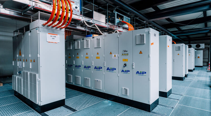
Volle Energie. Volle Kontrolle.
Testen Sie die Leistungsfähigkeit Ihrer Batterien unter realitätsnahen Bedingungen – von Lade- und Entladezyklen bis zu thermischem Verhalten und Alterung. Alle Systeme sind skalierbar und für Hochvolt-Anwendungen bis 1500V ausgelegt. Durch präzise Messtechnik und intelligente Automatisierung erfassen Sie verlässliche Daten für Effizienz, Lebensdauer und Performance.
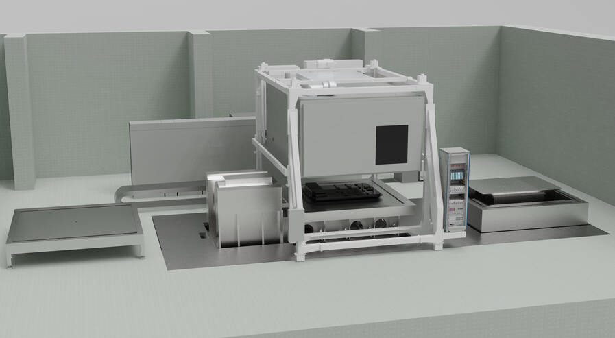
Batteriesicherheit testen
Simulieren Sie Kurzschluss-, Überlast- und Crushtests unter kontrollierten Laborbedingungen. Integrierte Sicherheitseinrichtungen, thermisches Management und automatische Abschaltmechanismen gewährleisten einen sicheren Betrieb in jeder Prüfphase. So prüfen Sie Batterien zuverlässig, reproduzierbar und normkonform – mit maximalem Schutz für Personal, Prüfling und Anlage.
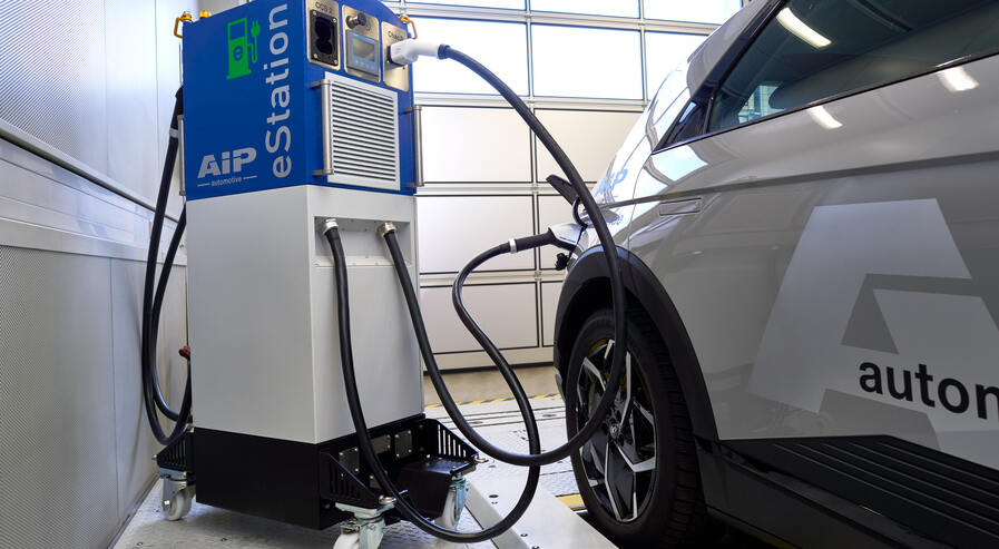
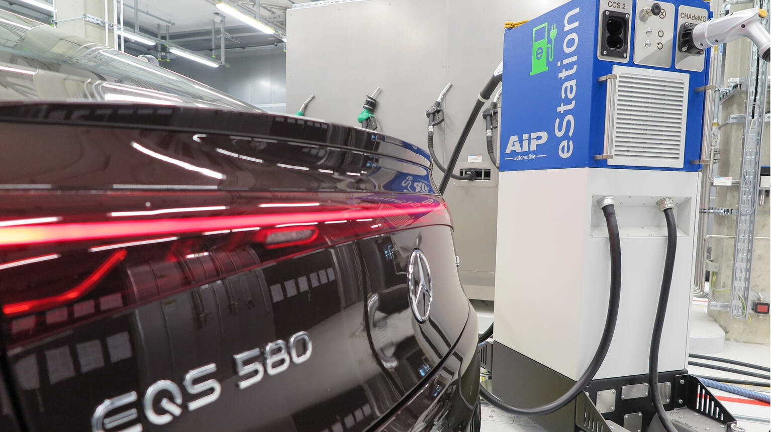
Ladeinfrastruktur für Fahrzeugbatterien
Sie verbinden HV-Ladeeinheiten und Kommunikationsschnittstellen direkt mit Ihrem Batterie-Prüfstand und erhalten Sie sichere, messgenaue Prüfabläufe. Modular aufgebautes Zubehör passt sich flexibel an unterschiedliche Batterie- und PackKonzepte an, sodass Sie Lade und Entladetests effizient durchführen können. Durch die lückenlose Integration reduzieren Sie Stillstandszeiten und steigern die Qualität Ihrer Entwicklungszyklen.
Batterieprüftechnik für jede Entwicklungsphase – vom Pack bis zur kompletten Batterie.
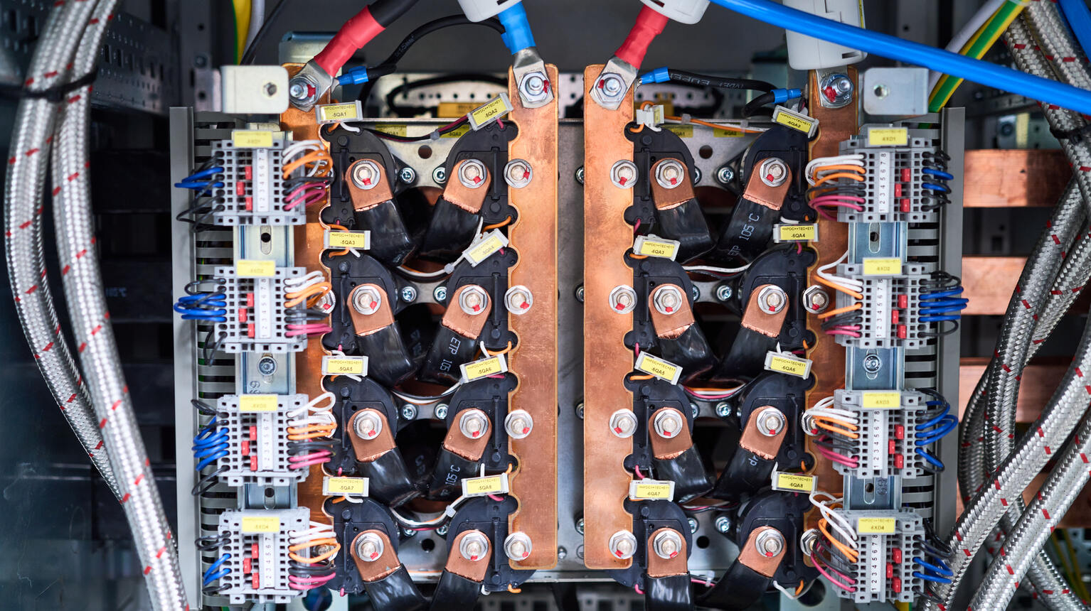
Komponentenprüfung – Sicherheit beginnt im Detail
Analysieren Sie einzelne Batteriekomponenten gezielt und normgerecht. Unsere Systeme ermöglichen präzise Tests von Leistung, Temperaturverhalten und Sicherheit – für eine effiziente Entwicklung und zuverlässige Integration in komplexe Antriebsarchitekturen.
Technische Highlights
- Prüfstände für Batterien und komplette Packs
- DC-Zwischenkreis für Energieeffizienz und Kostenreduktion
- Messung von Lade-/Entladezyklen und Temperaturverhalten
- Analyse von Alterung (State of Health)
- Abuse Test für Batterien unter sicheren Bedingungen
- Skalierbare Testsysteme bis 1500 V
- Kompatibilität mit automatisierten Prüfabläufen
Zubehör – Schnittstellen, die verbinden
Integrieren Sie Messtechnik und Ladeinfrastruktur nahtlos in Ihre Batterieprüfstände. Ob HV-Kontaktierung, Kommunikationsschnittstellen oder Ladeeinheiten: Jetzt nutzen Sie sichere, effiziente und messgenaue Prüfprozesse.
Einfacher prüfen
- Durchführung realitätsnaher Lade- und Entladeprofile
- Reproduzierbare Tests für Lebensdauer und Effizienz
- Sicherer Betrieb in Hochvolt-Umgebungen
- Flexible Kombination mit weiteren Prüfsystemen
- Effiziente Testplanung durch modulare Erweiterbarkeit
- Aussagekräftige Daten für Design- und Freigabeprozesse
- Zeit- und Kostenersparnis in Entwicklung und Validierung
- Optimierte Integration in bestehende Testumgebungen